Lilywatch Part2: The Build
This is a continuation of my previous posts regarding the Lilywatch: A watch built using an Arduino. This post goes over the building of the watch itself.
Process
Printing the Housing
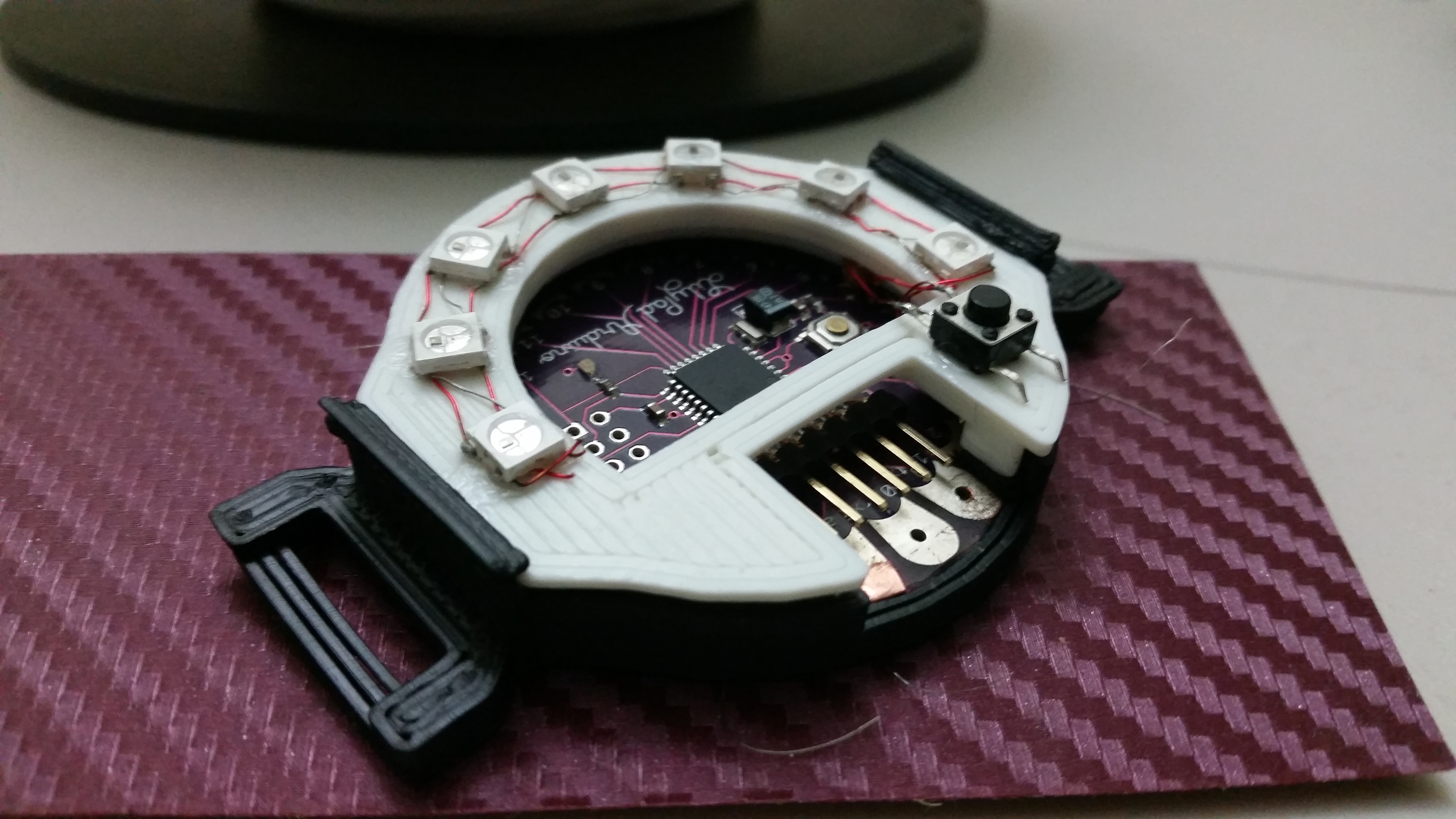
Since I already had a design from the last project, this was fairly easy. The only thing I did was make some improvements to the model. Namely I added holes in the bottom so connections could be made via the bottom of the watch. I wanted to do this because in the last project everything was attached to the cap, making removal of the cap difficult. That was a silly choice, but I learned.
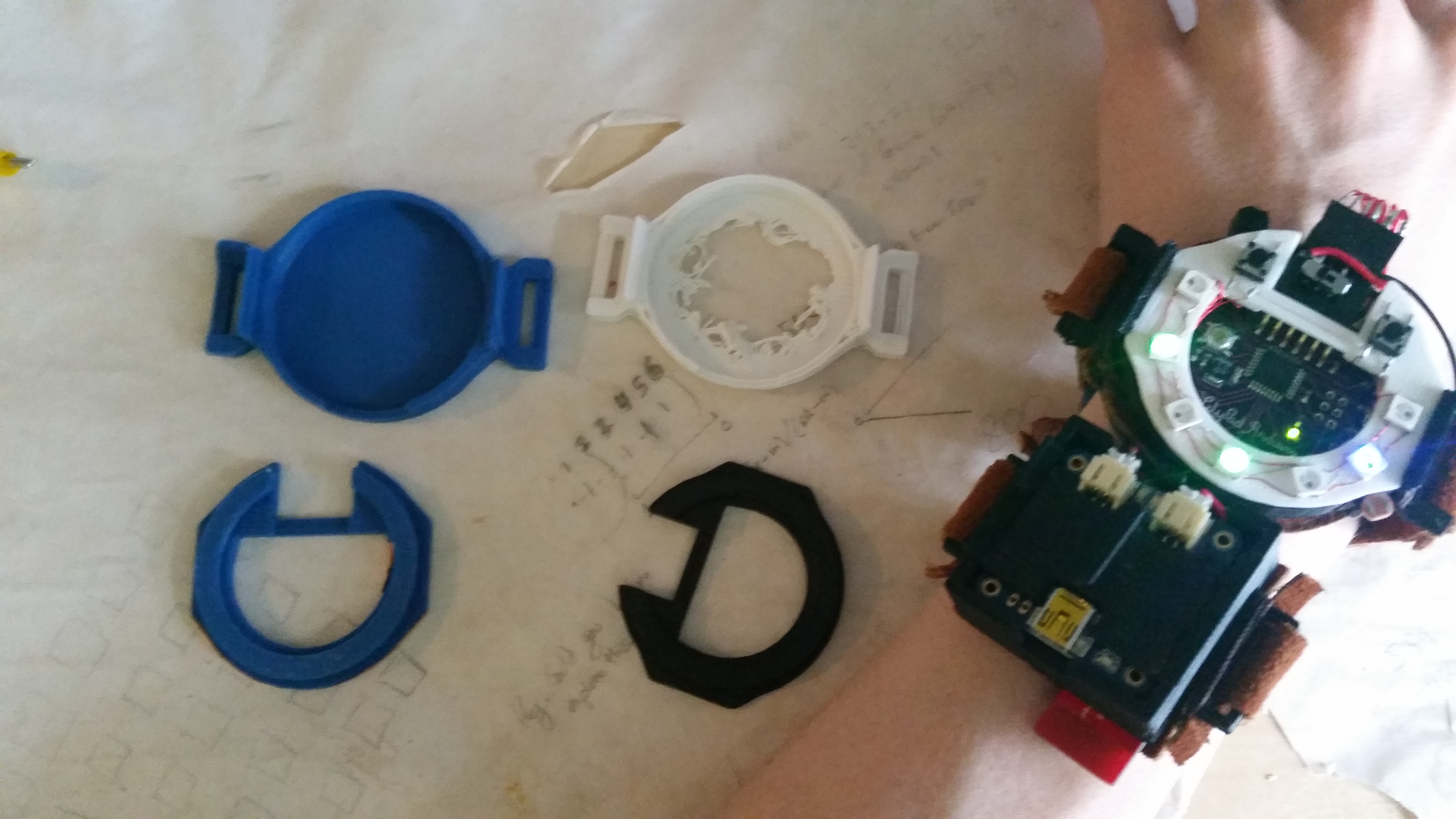
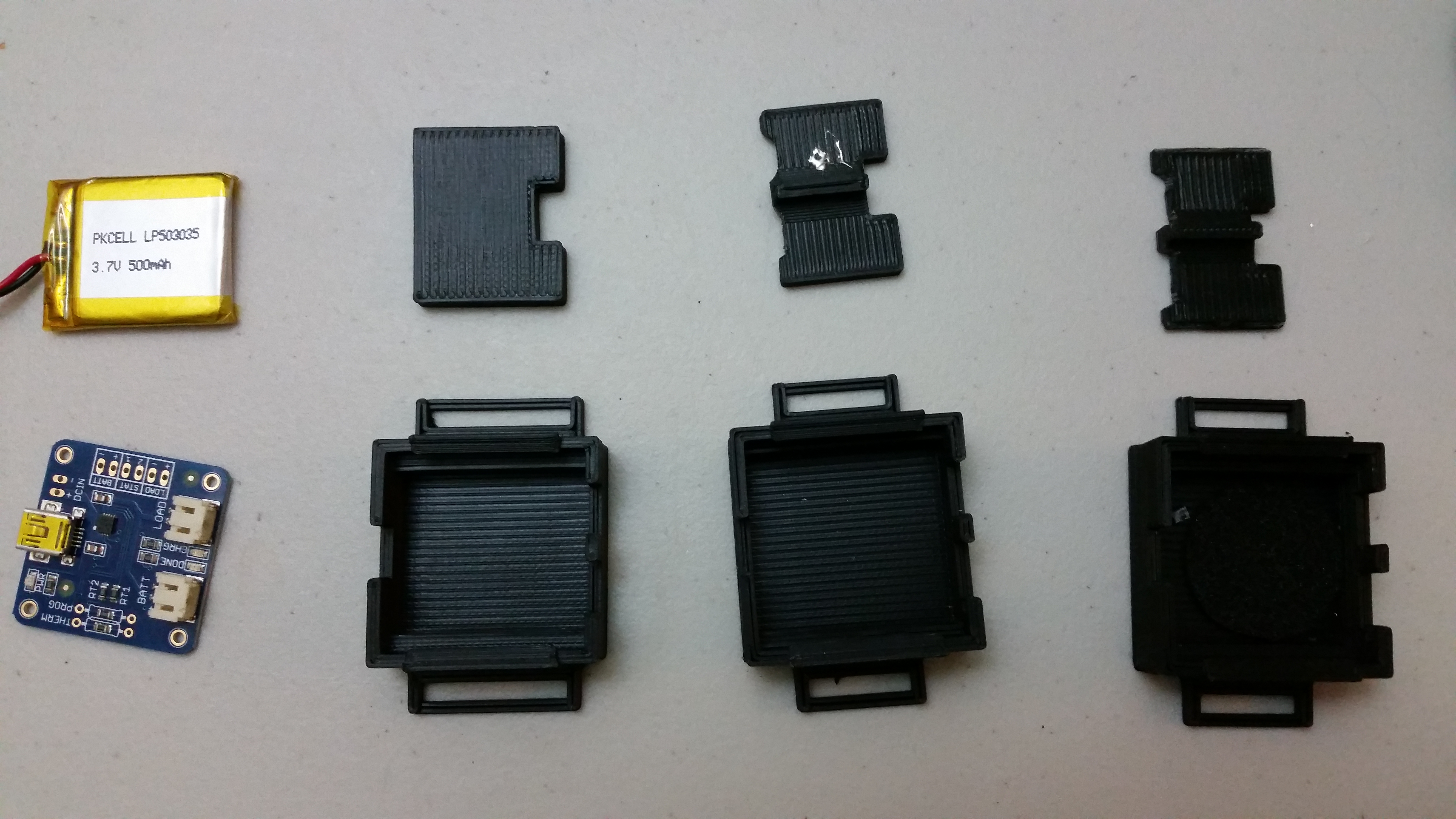
The battery housing had to be done from scratch for this project, though that wasn’t hard. It may not be pretty, it’s just a box, but it gets the job done. I wanted the battery to be it’s own entity because I wanted to keep the charging circuit on-board. I also made sure that the cap for the battery housing was quickly removable so that if something goes horribly wrong, as it occasionally does with batteries, it’s not so strongly fixed to my wrist.
Components
The Foam Ring
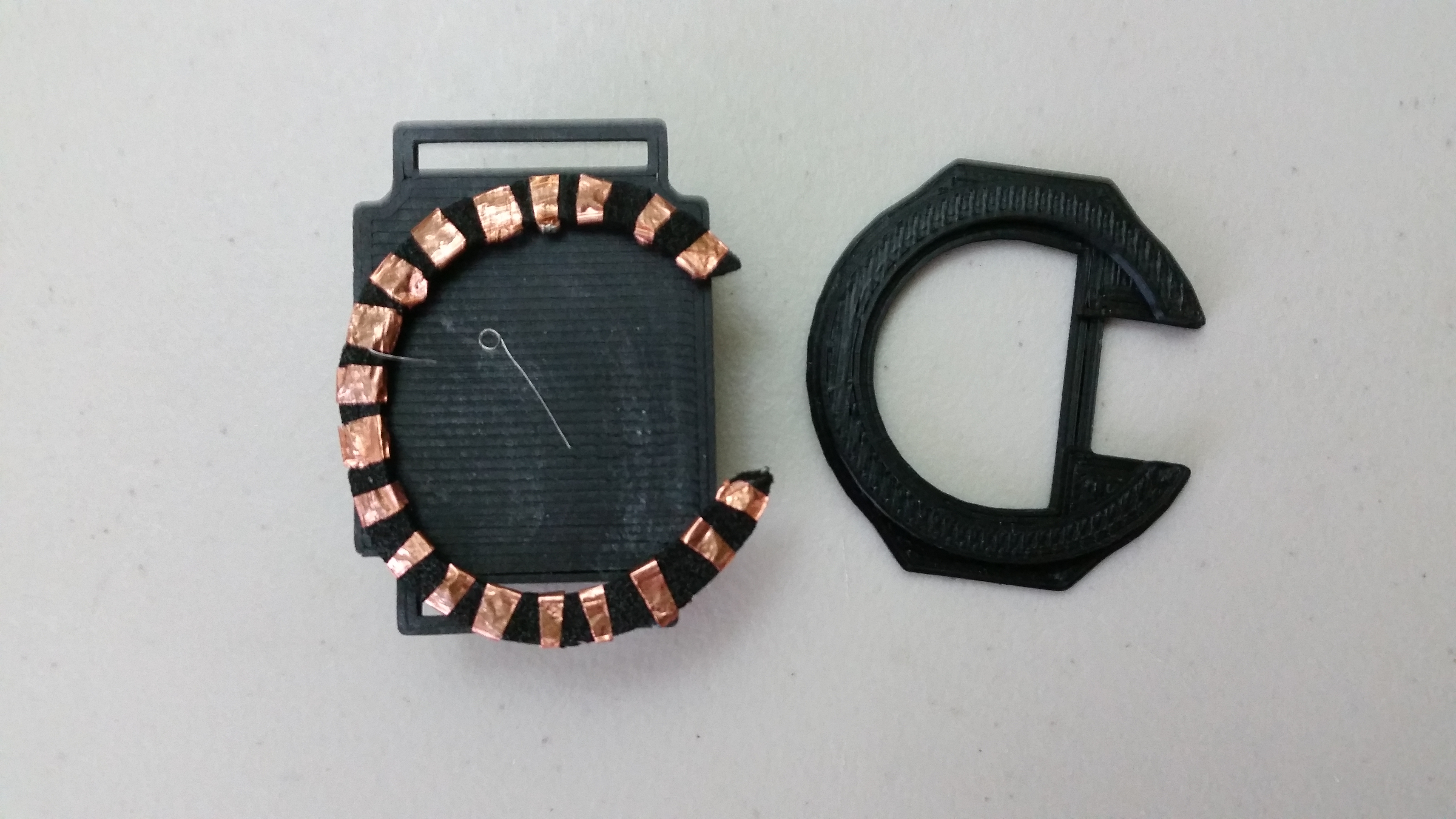
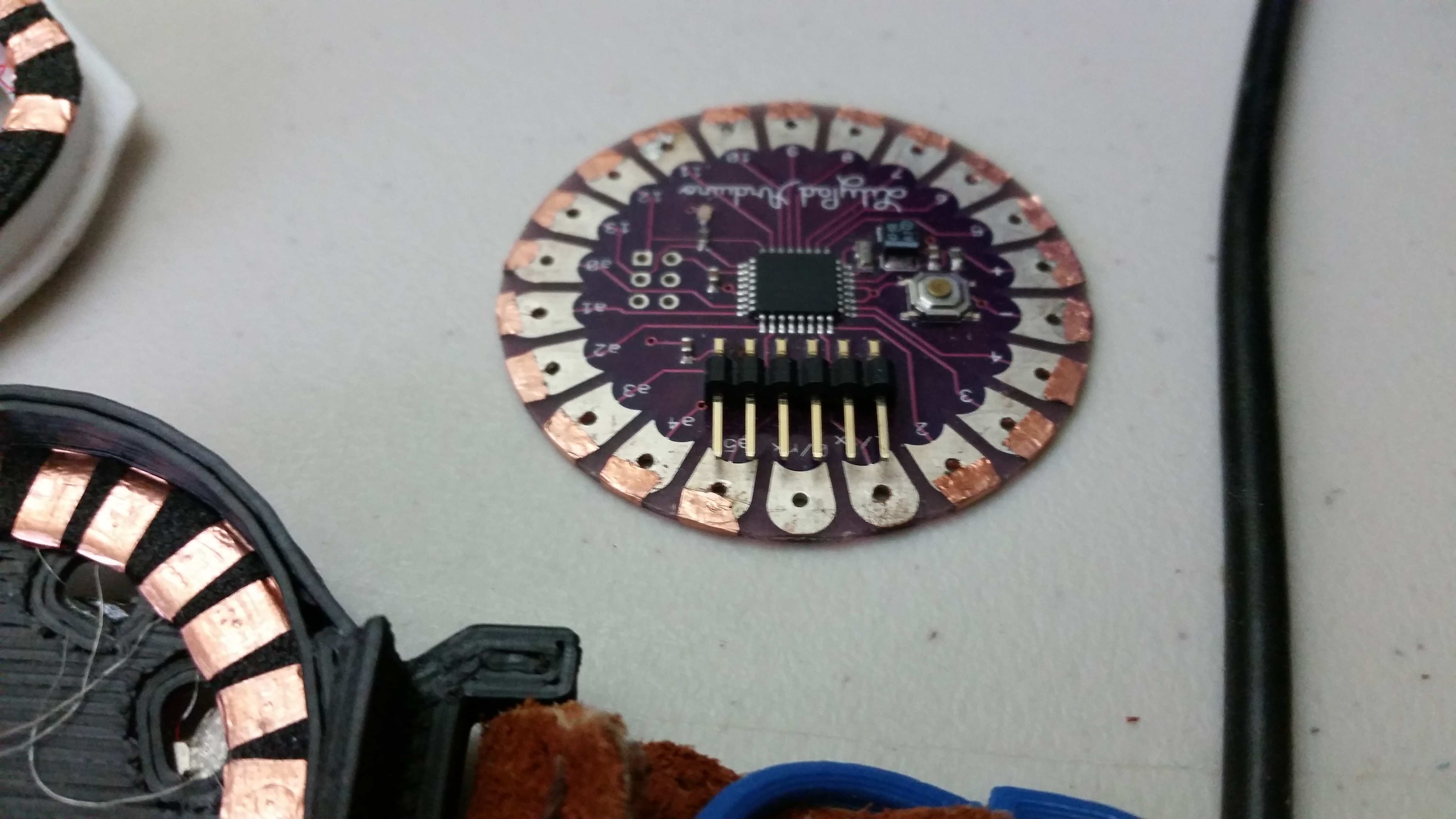
Similar to the last project, I used a foam ring to do make all the connections directly with the board. Using some 1.5mm thick foam I had laying around in my materials box, I cut rings for the top and the bottom of the board that matched the radius of the Lilypad and were thick enough to cover most of the metal pads on already the board. Then I took some copper tape and taped the ring wherever there was a pad on the Lilypad I thought I would use, and made sure to place a a small wire with a loop on the end between the layers of the tape (I only looped around a little more than once to leave an overlap). That wire would be what I would make my soldered connections to, since in the last project I learned not to solder directly to the copper pads. That melted the foam, made the pads too hard, and in general was a terrible mess.
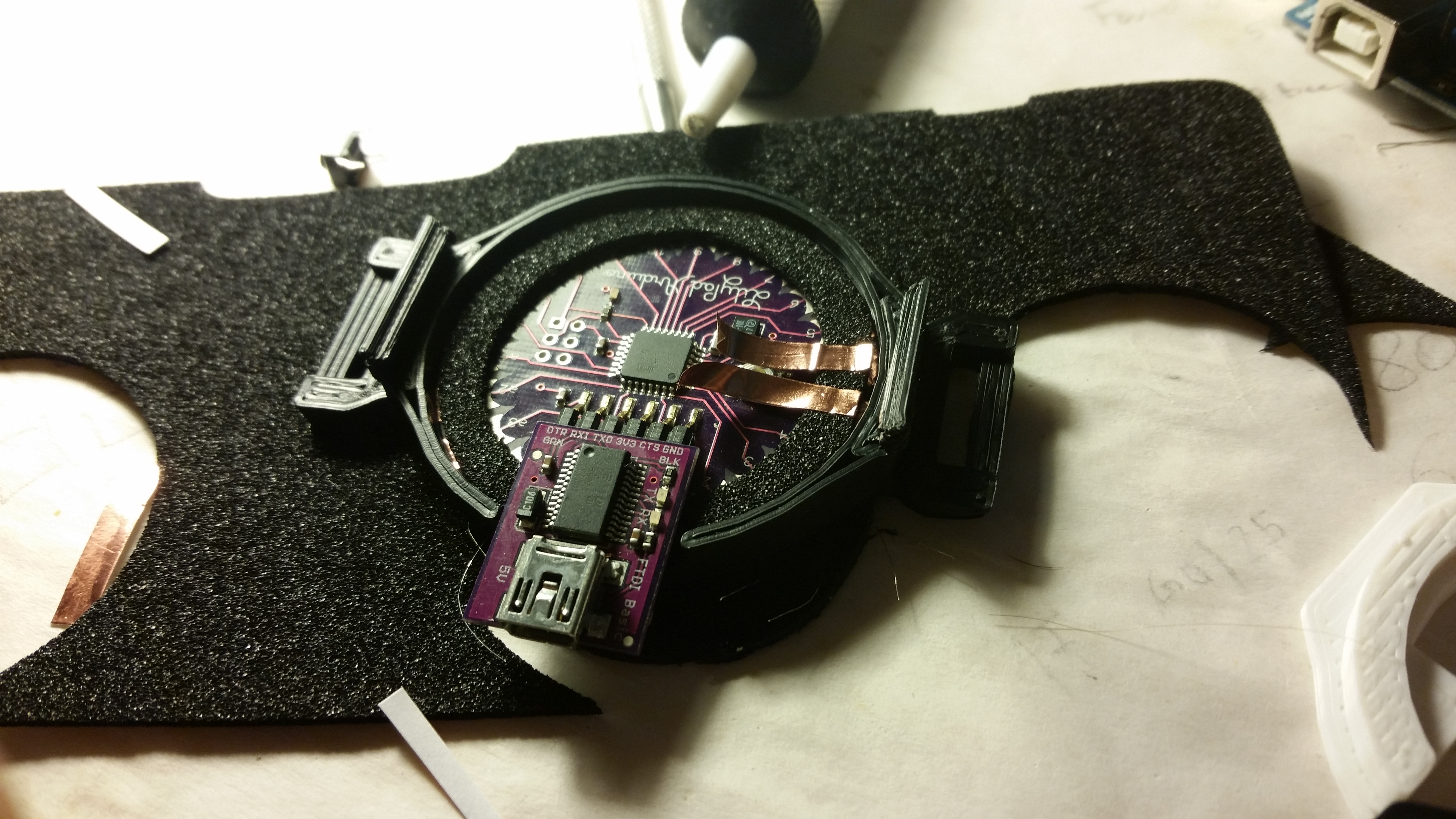
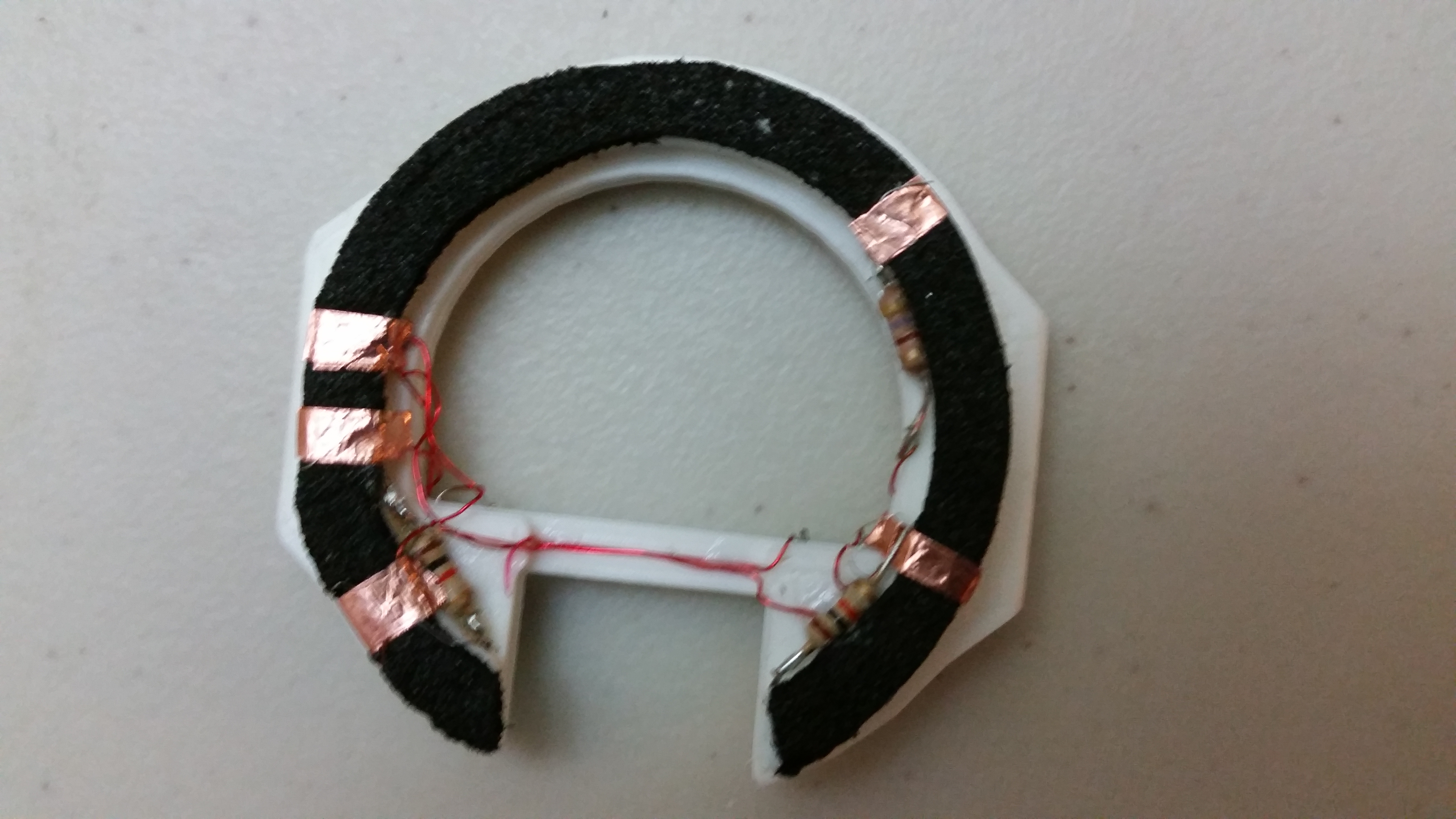
The bottom of the pad needed a little extra care, since the Lilypad I have doesn’t come with connection pads on the bottom. This was easily fixed though with a little more copper tape. I just needed to make sure I scraped off some glue so that a connection could be made between the tape and the pad.
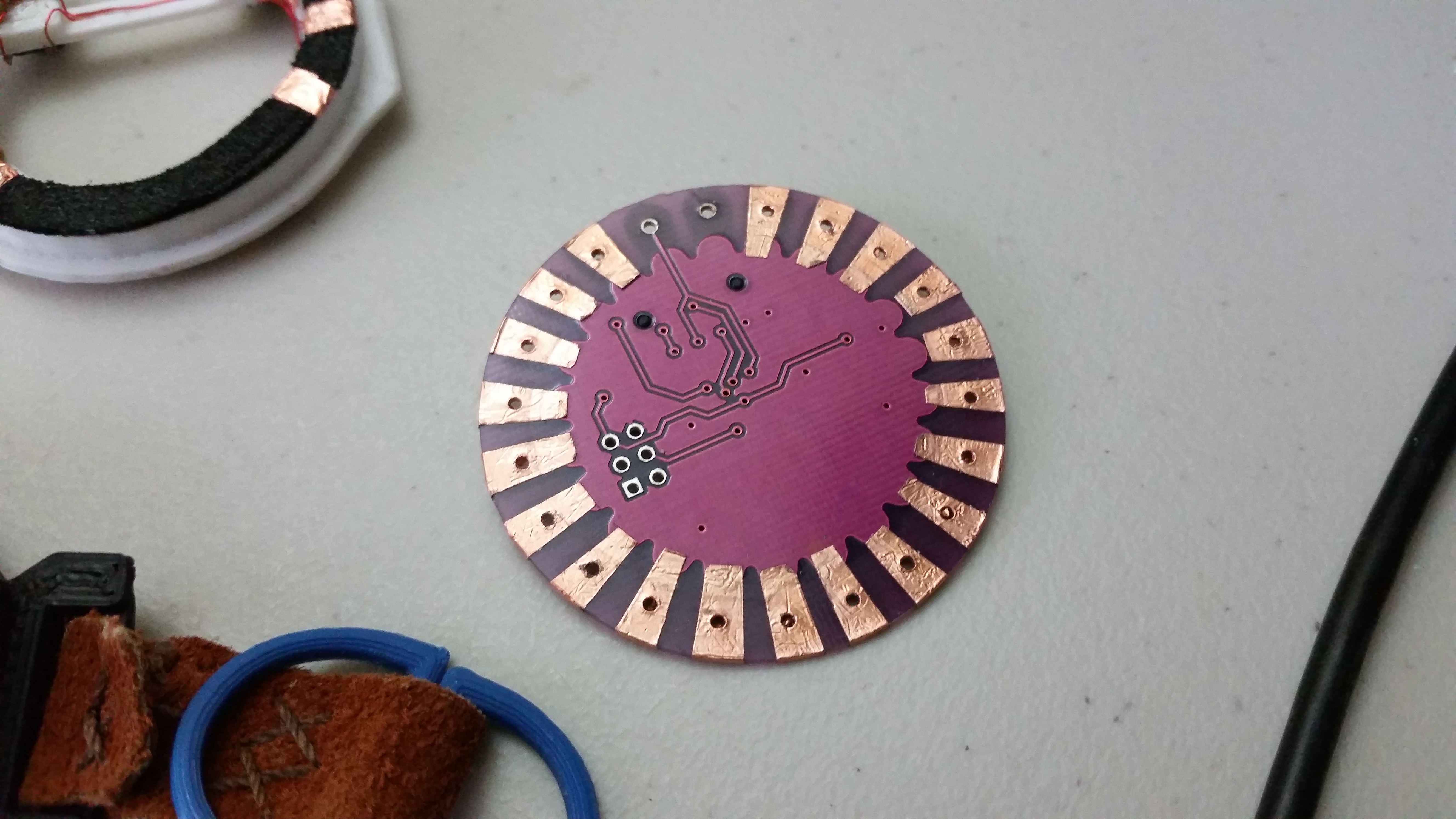
Neopixels
Neopixel attachment was kind of fun. This was mostly due to not having to sew through leather with my feeble, makeshift connectors. I was aware that there was already a product meant for this kind of project (see Neopixel Ring), but I knew I wouldn’t be using the full ring, plus I already had some perfectly fine Neopixels laying around.
To solder them, I made an indent in some sticky putty (meant to hold posters on walls) using the face of the watch and laid out the Neopixels where they should go in relation to the watch. This kept them in place relative to each other while I soldered the necessary wires together. Then it was as easy as pulling it off as one thing and gluing it to the watch face. I soldered the power and ground wires to the little connector wires I made, and tucked a resistor under the trim of the cap for the data wire. It all was falling into place better than I expected.
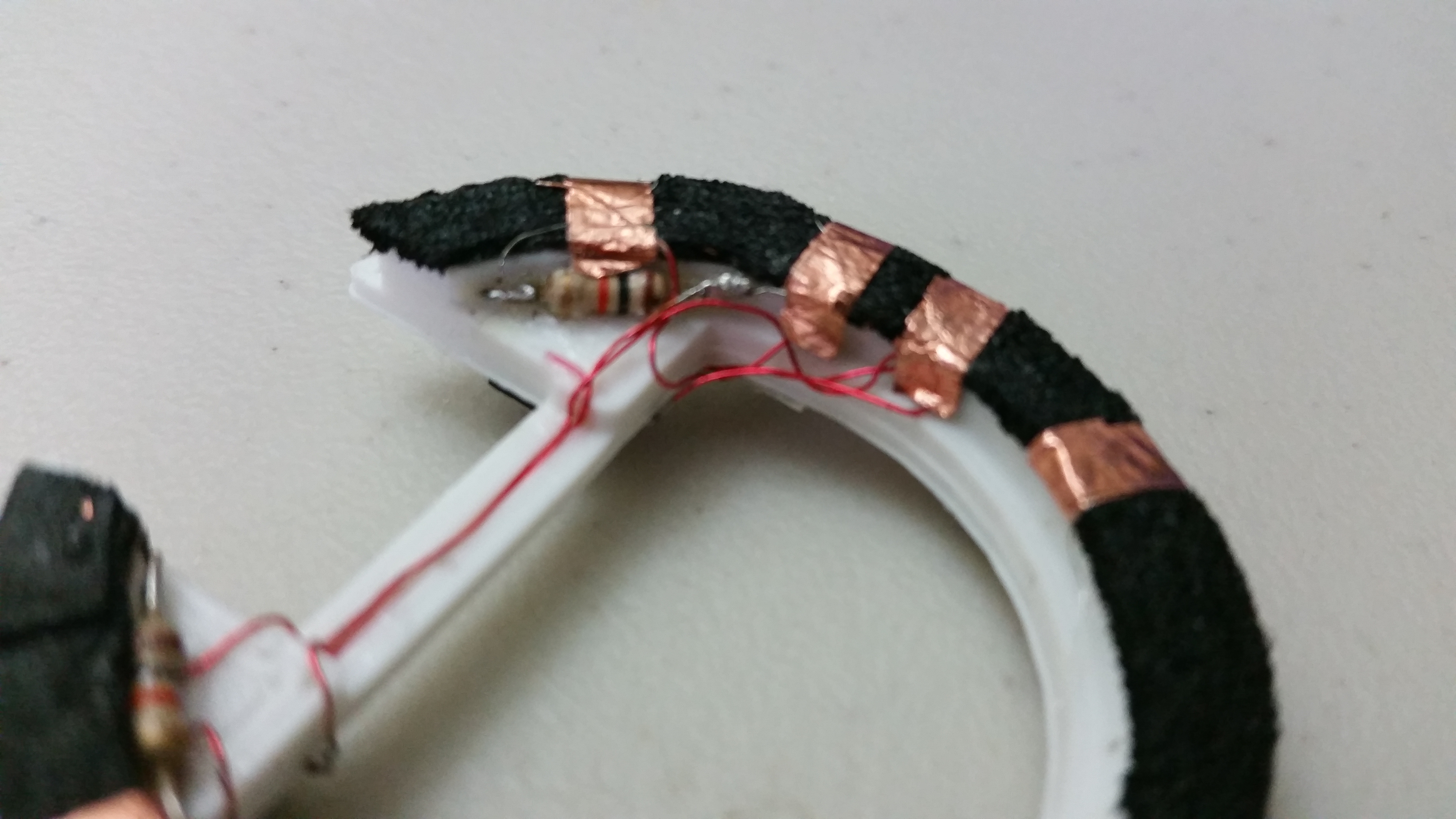
Bottom Motor and Sensors
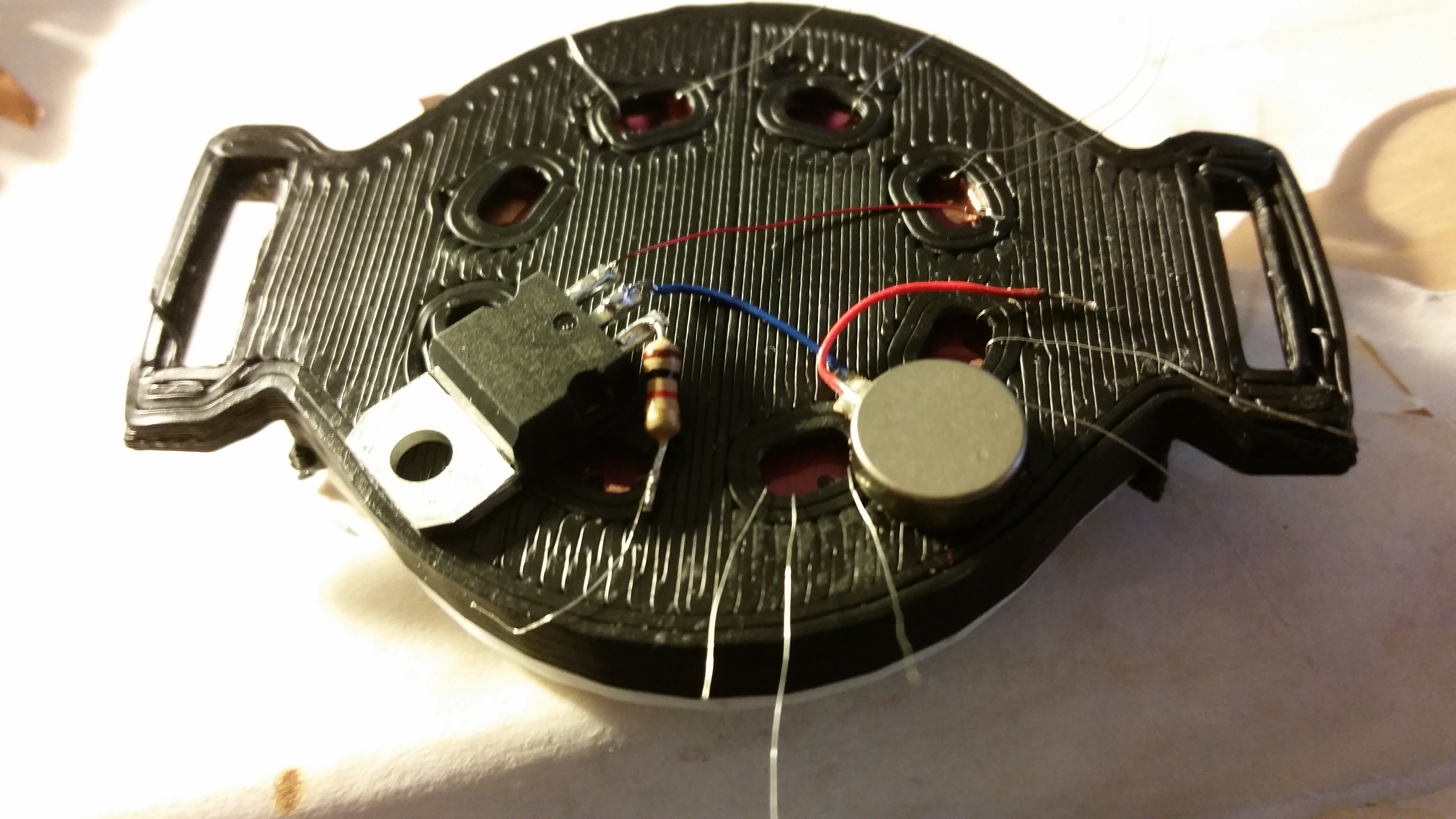
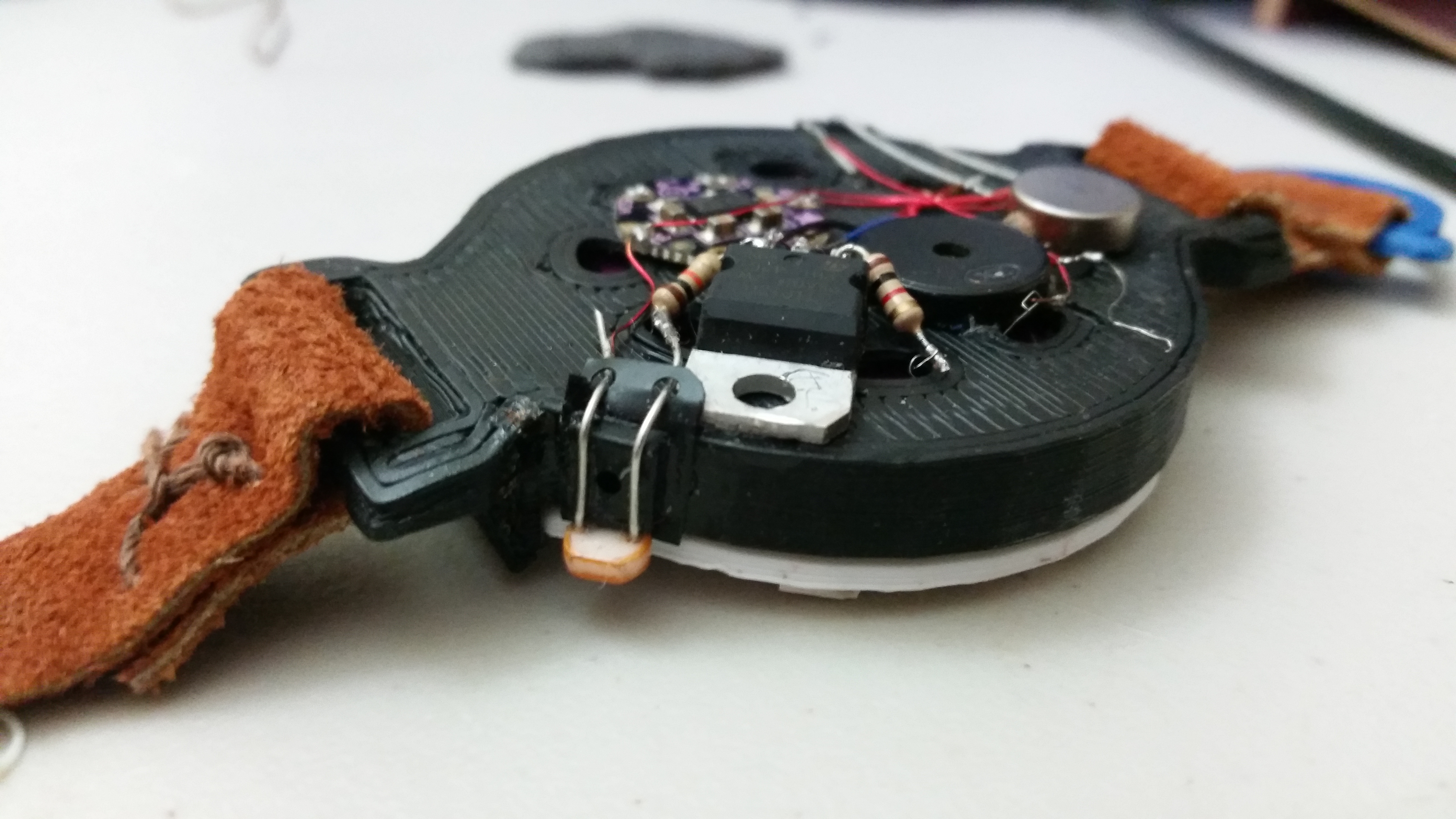
The bottom sensors were attached kind of hap-hazardly. I didn’t mean to do it that way, but I didn’t really have a plan for them since I knew I’d be adding more sensors later. I just didn’t know what. The vibration motor and its transistor went on first. I tried to make sure there was ample room for the future, but with so little room already, any effort made to that effect was unnoticeible.
Next came the Flora accel/mag sensor. I initally tried to make sure this wasn’t placed permanently, but I only had two types of glue: Superglue and rubber cement. Rubber cement was too weak to hold it and the Superglue was obviously too strong. I tried mixing them to dilute the superglue, but that was silly and messy and the part was still stuck too strong. Oh well.
The photo resistor came much later in the project, but adding it was pretty trivial. I obviously had to make the head of it peak out to the top, so I wrapped it up towards the cap and glued it to a square I cut off the little plastic thing the Neopixels came in. It fit miraculously well, and left the photoresistor tucked nicely into a corner.
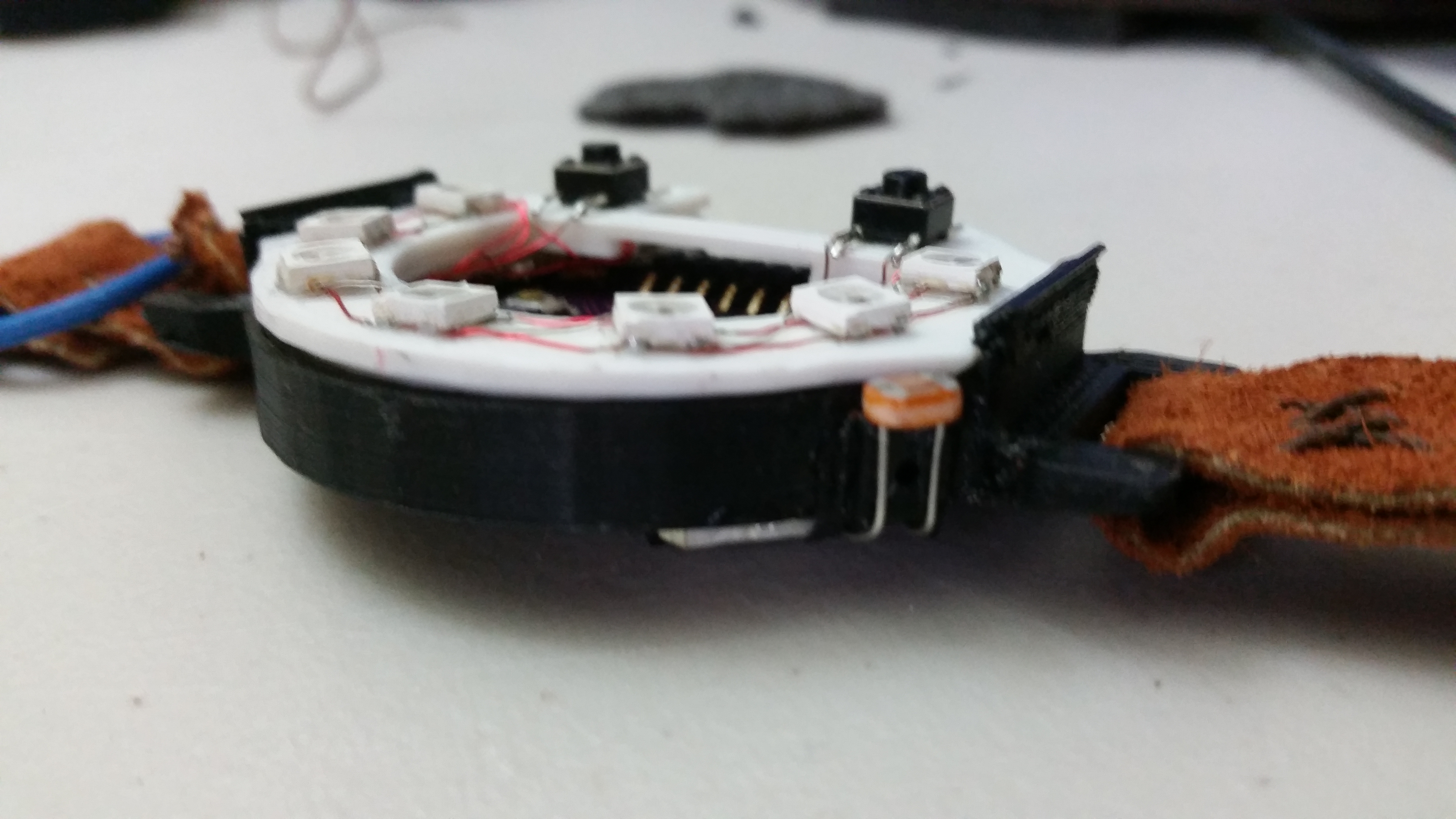
Leather and Straps
The leather for this was bought at Micheals (I’m pretty sure it’s not real). I just got a small square, enough for this project and a few others. I cut it to fit and tied it down with some string and volia! That’s done.
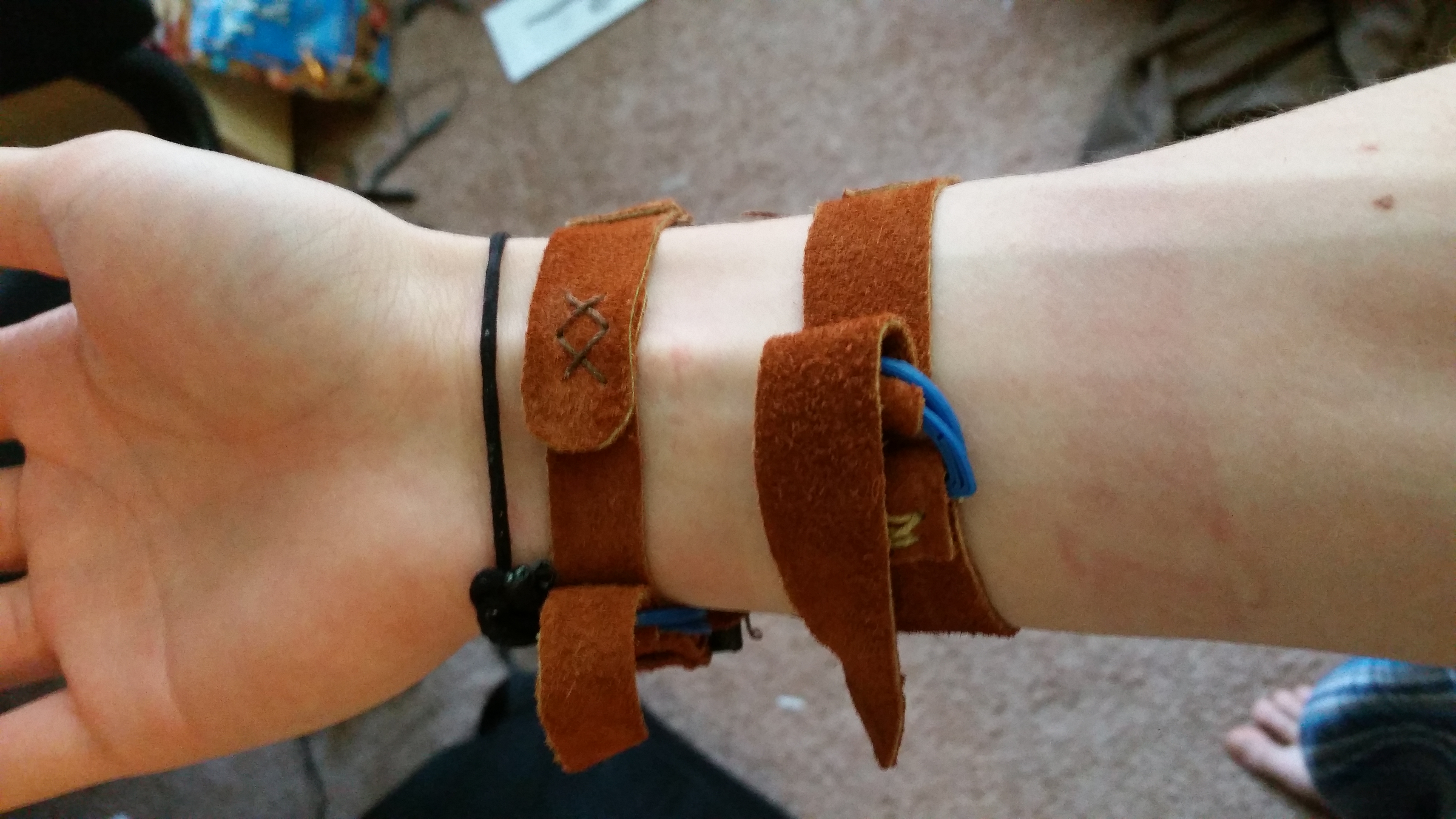
The leather on the bottoms of the watch and battery housings were there to prevent the components from being an irritant, which they were. The leather helped immensly.
Battery
I was kind of worried about the battery. I’ve had some pretty undesirable things happen to my cellphone batteries in the past, and I didn’t want to take any chances.
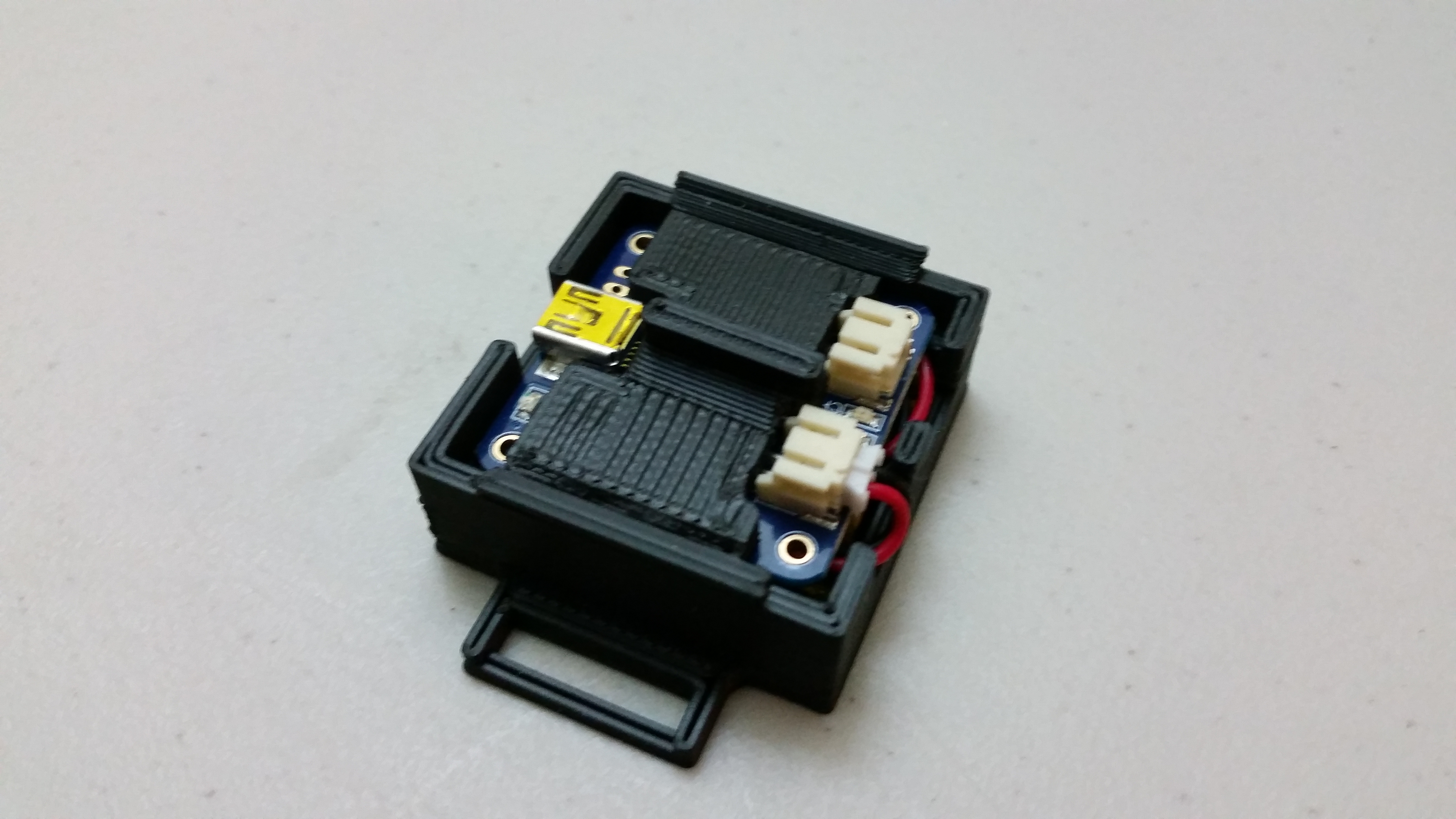
That is why I gave it its own housing with enough room to have the charging circuit. That way it doubled as protection and built-in charging. I mean, if I had to wear it around and it died, I’d like to be able to charge it without going home to fetch a charger box.
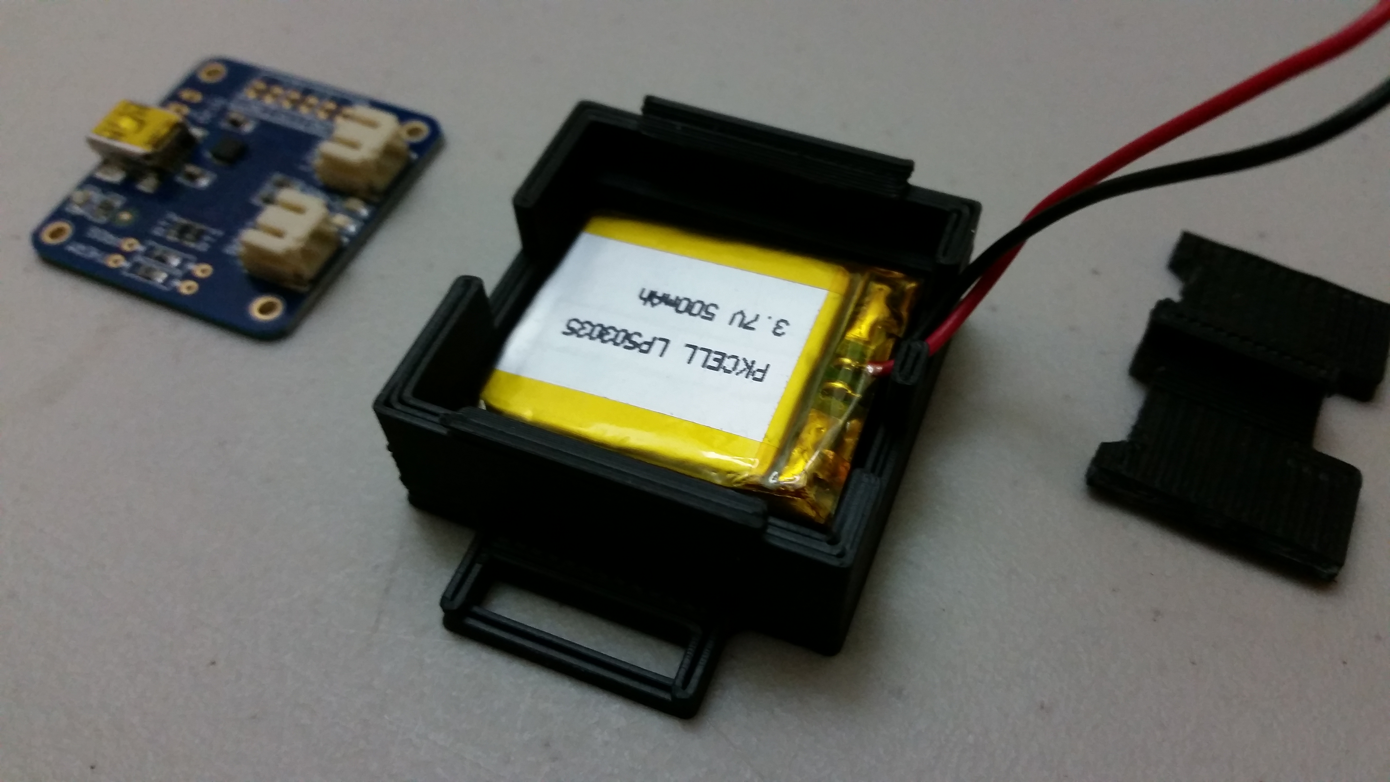
The battery box was pretty simple and strapped down like the watch itself. It also has a cap, but with the way its designed this cap was not really meant to come off as easily. The cap was designed to fit around the plugs of the charging circuit and the two clips holding it in place were much sturdier, preventing them from bending back. I took advantage of the bending clips on the watch face so that it was removable, but I knew I wasn’t going to be removing the battery very often and I’d rather have it secure. In fact, the cap is so secure it took a screwdriver to get the clips to bend at all during one of the iterations, so for the final cap I added a middle wall which allowed me to sort of push the cap to one side while bending the opposite clip, releasing it only when I intend to.
Wiring plug
To go along with removability, the plug for the battery was attached to the pins intended for the USB cable. The plug was simple, it provided a switch as well as continued pins so that I could plug things in behind the plug. Namely this was for the Bluetooth module.
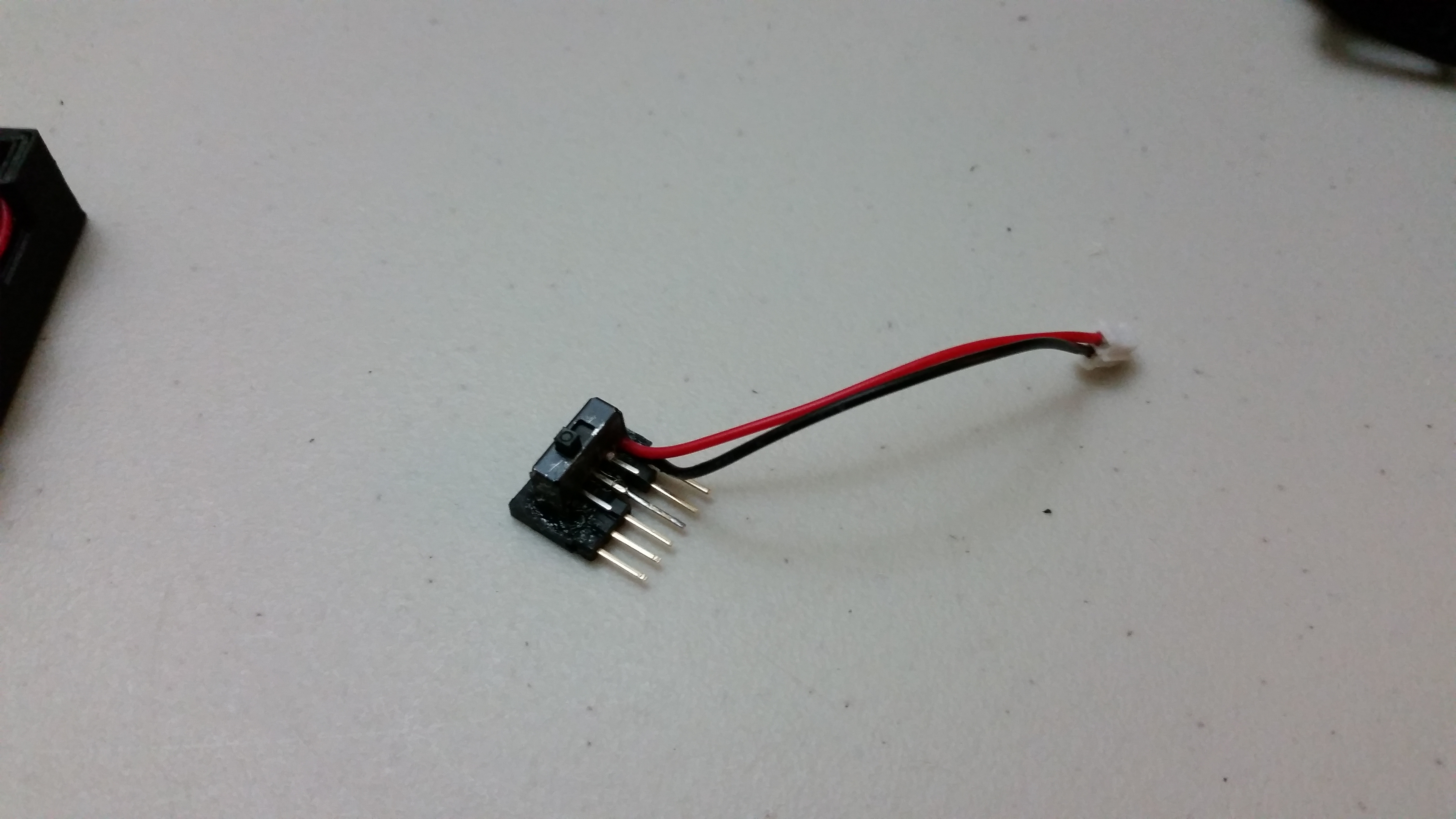
The wires for this were a little frustrating. The connections kept breaking due to being moved around so much. I tried to hold them in place using various things wrapped around to keep the connections together, but all proved fruitless. The biggest hassle was between the JST connector its wire. What I eventually found was that using solid wire as opposed to bendable, stranded wire made for a more lasting connection.